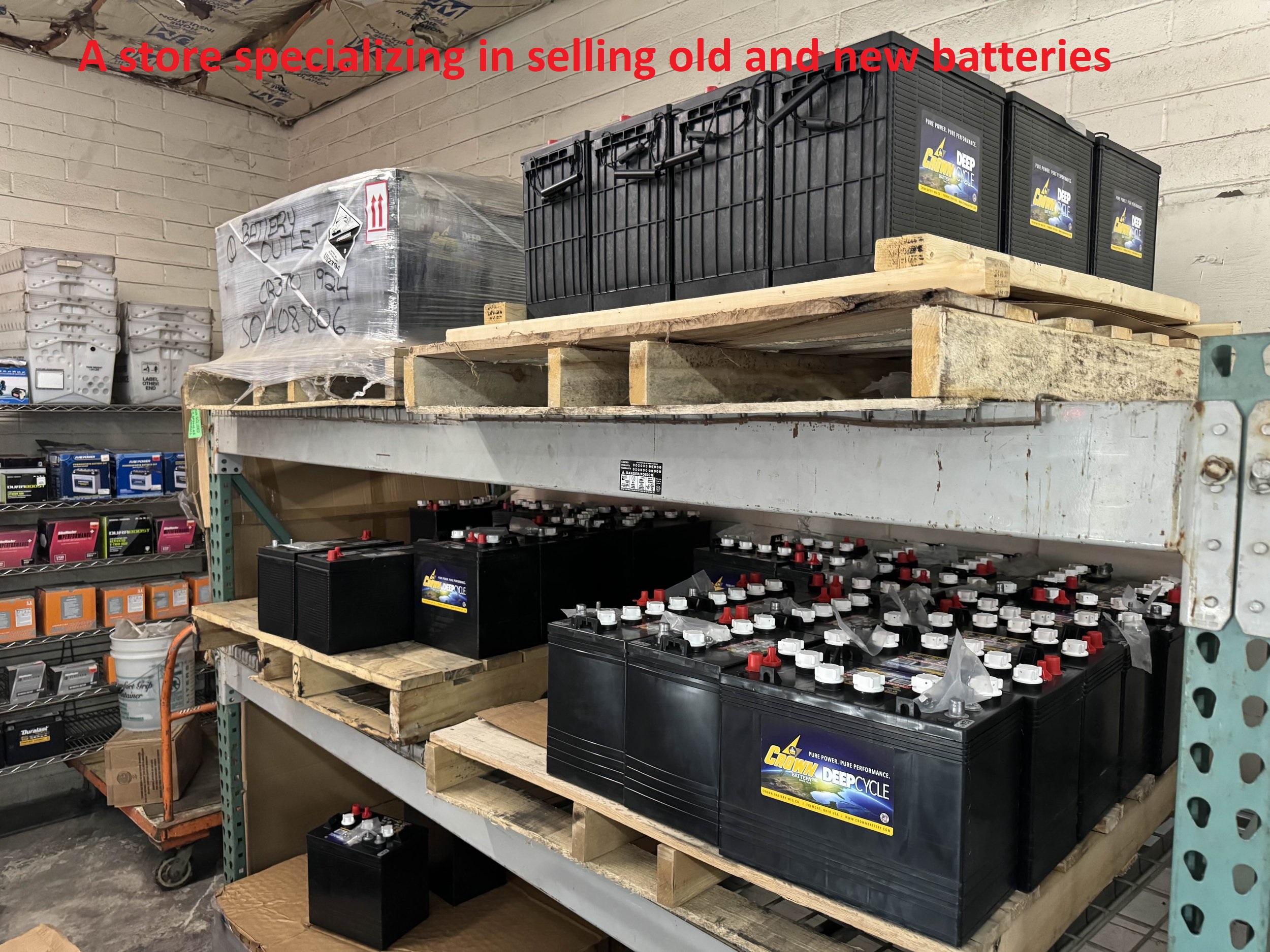
A fairly simple and practical way to generate electricity for household use is by using batteries (lead-acid or deep-cycle) and an inverter. This setup is considered a basic model and is not recognized by academia as a “free energy” system, because you still need to spend energy to recharge the batteries.
 |
| Just 2 batteries with high Ampere hour rating can power a house if it is charged by free energy. |
However, a system with multiple interconnected batteries can produce what many call free energy. This concept has been around since the 1980s and has been explored by engineers who think outside the box. Although many variations exist based on inventions from the ’80s to now, very few people implement them, largely because this type of technology is hidden and never taught in schools.
Many people immediately think of John Bedini’s pulsed battery charging systems from the 1980s. And yes, Bedini became famous for his "cold electricity" charging method and his pulsed battery chargers. But he also developed many other systems that used batteries to store free energy, including a practical version of Tesla’s pulsed battery charging concept.
According to this principle, if the batteries are connected using specific electronic components and devices, they can charge each other in a near-continuous cycle. This is a simple model for accessing free energy.
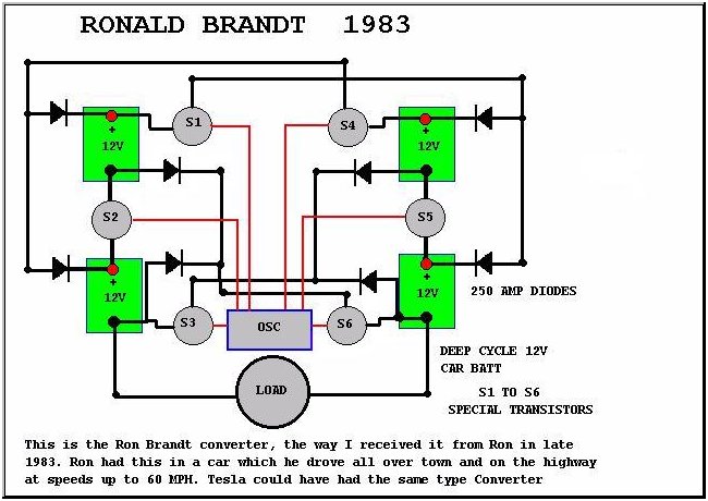
Circuit Diagram:
As shown in the diagram, there’s a pulse generator - an IC SG1524 Pulse Width Modulation (PWM) Controller. The rectangular block in the diagram represents the IC SG1524, which generates control pulses to switch the transistors on or off.
 |
| Block diagram based on Bedini's invention to clean the engine on the car. |
On the left side, there are two batteries and three switches (three transistors) — two switches for the positive terminals and one for the negative.
Operating Principle:
The OSC SG1524 opens all three left-side transistors. When this happens, the transistors amplify the current to charge the two batteries on the right side. During this moment, the right-side transistors remain off.
Meanwhile, the left batteries also power a brushless DC motor. When the IC SG1524 produces a zero-voltage pulse, the left-side transistors turn off for a short interval. At that moment, the coil inside the brushless DC motor is suddenly cut off, collapsing its magnetic field, and this generates a reverse pulse that recharges the left-side batteries.
Even though the left-side batteries consume a lot of energy - both to power the motor and to charge the right-side batteries - they are recharged with a larger burst of energy when the SG1524 pulse goes to zero.
That return energy is more powerful because the magnetic field inside the motor's coil collapses rapidly, almost at the speed of light, creating a high-voltage pulse known as “cold electricity,” which charges the batteries.
This recharging phase occurs precisely when the transistors are turned off (during the 0V pulse). Then, a new pulse is emitted by the remaining output pins of the SG1524, activating the three right-side transistors. The same process now occurs in reverse: the right-side batteries charge the left ones while powering the DC motor, then a reverse pulse is sent back into the system when the current is cut again.
This system continues to operate indefinitely - until the batteries or the motor physically break down. But that's not all. We only observe the free energy visually through the spinning DC motor and the batteries that seemingly never need recharging.
In fact, free energy also accumulates at the terminals between batteries, where “cold electricity” charges them continuously. From these points, you can connect additional batteries to siphon off energy and charge more units.
The 4-battery setup is simply a baseline configuration for mutual charging. Once it's running with the motor, the terminals become power hubs for other batteries to be connected and charged.
So, if you have a high power load, you just need to add more batteries with a higher amp-hour rating, and get a larger inverter. That's it - your system is ready.
Practical Application
We can apply this model to generate kinetic energy to power machines or even supply electric cars without the need for external charging. The main source of kinetic energy is the DC motor shown in the circuit diagram.
As mentioned earlier, the terminals of the four batteries also act as sources of free energy.
Initially, you can run the system using nearly dead batteries, which will gradually charge up. The system actually works better with old batteries rather than new ones, because the "cold electricity" pulse from the DC motor coil won’t damage or explode older batteries. If the batteries are too weak to start, the motor can be manually spun to kickstart the process.
 |
| The 3 battery set will work well with old batteries |
Once the system is running steadily, you can connect additional high-capacity batteries to be charged. Then, add a high-power inverter to generate usable AC electricity.
AB, CD, EF, and GH = Charging points for the larger batteries
These large batteries will then feed into the inverter.
High-capacity batteries (with high amp-hour ratings) are recommended. Lead-acid batteries are preferred, as they are safer and better suited to accept the high-efficiency charge from cold electricity.
Here is a list of electronic components and electrical equipment according to Bedini's implementation, to apply to create free electricity for the home:
Component | Description / Specs | Check & Buy |
|---|---|---|
SG1524 PWM Controller IC | 16-pin PWM controller IC generating pulses for switching transistors (8–40 V supply range) | |
NPN Transistor (e.g., 2N2222) | General-purpose transistor used as a switch; handles ~40 V, 0.6 A (alternatives: MMBT2222, 2N3904) | |
Brushless DC Motor | 12–24 V brushless motor; coil produces regenerative "cold electricity" pulses | |
12 V Deep-Cycle Battery (e.g., 100 Ah) | Sealed lead-acid battery for energy storage; designed for deep discharge cycles | Check price / Buy | |
Power Inverter (12 V DC → 220 V AC) | Converts battery's DC to household AC power; choose 1 kW–2 kW rating depending on load | |
Diodes & Bridge Rectifier | Diodes used for directing charge flow and generating pulses; bridge rectifier used in regenerative circuit | Check price / Buy | |
Power MOSFETs (optional) | High-current switches used in place of BJTs for improved efficiency and higher power handling | |
Passive Components | Includes resistors, capacitors, inductors used for timing, filtering, and controlling PWM circuit |
Recommend you a set of books including many sets of books with detailed instructions for each step to generate free electricity at home:
Conclusion:
It is the load itself that generates free energy within the coil. This happens because the dielectric field (magnetic field) collapses suddenly at a speed close to the speed of light, producing a high-voltage pulse that compresses along the wire in the form of "cold electricity" to recharge the battery. Even sulfated batteries can be restored and charged beyond their rated voltage using cold electricity—without risk of overheating or explosion.
This system is simple and requires only batteries and basic electronic components. The DC motor increases efficiency thanks to its rotating magnetic field, which spirals inward and amplifies the dielectric energy.
The dielectric mentioned here refers to the dielectric of the field—that is, the dielectric of the aether when disturbed. Magnetic fields, electric fields, current, and voltage all ultimately originate from the dielectric.

